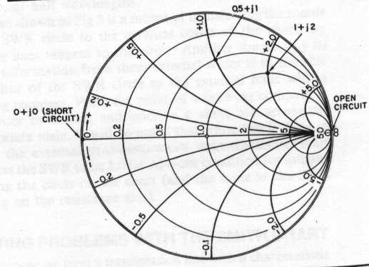


The open-circuit stub location in wavelengths from the amplifier load interface is a function of the clockwise angular difference between point "A" and GammaL. 'BackgroundColor', 'Position',)Īnnotation(container, 'arrow',) Calculate the Stub Location and the Stub Length for the Output Matching Network 'HorizontalAlignment', 'center', 'FontSize',8. These reflection coefficients are measured at the amplifier interfaces.Ĭircle(amp,freq, 'Gamma',abs(GammaL),hsm) Calculate and Plot the Complex Load and Source Reflection CoefficientsĬalculate and plot all complex load and source reflection coefficients for simultaneous conjugate match at all measured frequency data points that are unconditionally stable. This example uses the YZ Smith chart because it's easier to add a stub in parallel with a transmission line using this type of Smith chart. Stub tuning is one method that satisfies both of these criteria stub tuning is simply the process of adding a length of transmission line to the existing length in either series, shunt, open circuit, or short circuit configuration to match the line to the load. At this location, the stub will negate the transmission line susceptance, resulting in a conductance that equals the load or source terminations. Movement along a transmission line is equivalent to traversing a circle centered at the origin of the Smith chart with radius equal to a reflection coefficient magnitude.Ī single transmission line stub can be inserted at the point on a transmission line when its admittance (transmission line) intersects the unity conductance circle. Example of matching network with a single open stub (similar to. The simplest termination is either a short circuit or an open circuit.The center of the Smith chart represents a normalized source or load immittance. 0:00 / 11:23 UCLA EE101 Smith Chart Philip Hon 252 subscribers Subscribe 204 72K views 10 years ago Recap of Smith Chart. This free online interactive Smith chart tool is a calculator which can help you design matching networks and obtain maximum power transfer between your source and load. Matching with Parallel / series L or C But no explanation on how to find the ZL if I have a series open/short stub with a given length Additional 'boundary condition' to the solution: AFAIK in the exam we are only given a Impedance Smith chart, no admittance Smith Chart. The impedance to be synthesized is reactive so the termination must also be lossless. Inserting parallel Open/short stubs and finding out the length 4. Figure 2 - M1 is at 100.217 MHz as that is the SC frequency point for an open ended stub which will be infinity impedance.


 0 kommentar(er)
